Frequency shifters add an exotic dimension to the world of modular synthesis signal processing.
A basic definition of the Frequency Shifter process:
A Frequency Shifter takes the individual frequency components of the input signal and shifts them by the same number of Hertz, producing a subtle or dramatic effect on the tonal character of the sound.
Unlike a Pitch Shifter, The frequency components are translated rather than transposed.
Harmonic relationships are not preserved as harmonic overtones become inharmonic partials.
Mp3 demos:
S.A.R.S..mp3 441k
An example of voice processing with the FS.
Radio discussion of a disease that has put Toronto on the map.The up and down shifted signals are panned left and right in the stereo field.
Kneel Jung.mp3 1094k
Folky turns Alien. Up and downshift panned left and right.
barberpole.mp3
If the output is patched to a mixer and then feedback to the input and mixed
with the source signal, barber pole phaser type sounds with apparent 'perpetual
rising' effect are possible.
Frequency Shifter in use:
Small amounts of shift can be used to produce phasing/chorus effects or alien/chipmunk
voices. Large shifts will impart a metallic or clangorous quality to the signal. Spectral
inversion is possible with large negative shifts. The frequency shifting process
generates simultaneous up shifted and downshifted versions of the
input signal. Both outputs are available at separate jacks (SUM and DIFF)
on the front panel.
Shifting through-zero hertz reverses the function of the outputs making up shift become downshift and vice-versa. With both outputs panned left and right unusual stereo image effects are also possible.
- Features:
- Low-distortion wide-range
- Thru zero quadrature oscillator design
- Stable at small shifts.
- On-board Compander with auto gating
- Excellent carrier feed-thru performance and rejection
- Hand matched components for accuracy in the dome filter
- Extra Large (1-3/4") graduated shift knob for precision control
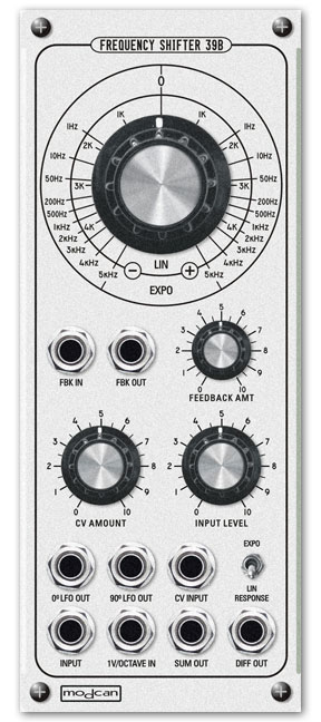
Feed Back Loop IN and OUT
Feed back loop for insertion of external modules
for processing the feed back signal.
An exellent example is the Super Delay 30B
With no plugs inserted the feedback path is normalled and the panel feedback amount control sets the depth.
Swirling barber pole phaser type effects are possible in this mode.
Demos created with delay module paqtched in the feedback loop of the Frequency Shifter.
mp3_1
mp3_2
mp3_3
mp3_4
1V/Oct Input
When in EXPO mode the 1V/Octave can be used to
track a keyboard. Interesting results can be had by tuning and tracking an un pitched sound source like pink noise.
mp3 example:
Tuned noise.mp3
Pink noise 'tuned' by the FS
CV Input
Control Voltage input with panel attenuator
for CV modulation of the shift amount.
Response Switch
Select between Exponential or Linear response.
This is a global function that affects the response of
the main shift knob control and the cv inputs.
Sum and Difference Outputs
Sum and Difference Outputs:
Outputs for up and down shifted signal
Specs:
+/- 5kHz knob shift range (greater with CV)
Output impedance: 1k ohms
Control Sens:
1 Volt per Octave (Expo mode)
1 V per 1kHz (Linear Mode)